
Unit 1, Where The Melted Fuel Is
Update: The source for unit 1 torus radiation had an incorrect link. The correct link has been added to the page. Documentation for unit 1 torus radiation can be found here on our site http://www.simplyinfo.org/?p=6340 or directly from the TEPCO handout here: http://www.tepco.co.jp/en/nu/fukushima-np/images/handouts_120627_02-e.pdf
The fukuleaks.org/web research team has been following and documenting the events in Unit 1 since March 11, 2011. As part of our ongoing research into the Fukushima Daiichi nuclear disaster.
Many pieces of new information have come out in recent weeks since TEPCO sent workers in to investigate the containment of unit 1. This has added new pieces to the big jigsaw puzzle of information on unit 1. One of the significant pieces of information is that the radiation levels inside unit 1’s containment are quite low. Inside unit 1’s containment the highest reading found was 11 Sv/h. The highest TEPCO documented inside unit 2 was 72.9 Sv/h. We calculated an estimated radiation reading in the pedestal of unit 2 to be somewhere between 5 gigaSv/h to 10 teraSv/h*. There is a very clear difference between the two containment findings. The radiation readings inside unit 1’s containment were unexpectedly low. It would be impossible to have the bulk of the melted fuel inside unit 1’s containment with those low radiation levels.
We show where the varied radiation levels have been recorded in unit 1 in the diagram below. The top of the reactor well on the refueling floor was 60 mSv/h, a comparatively low reading. Areas on the turbine (east) side of the reactor building and associated connected structures that lead to the turbine building show high levels that raise the closer you go towards the east side torus region. In this reactor design the torus sits partly under the reactor building that can be clearly seen above ground. The other portion of the torus sits in the basement level that is outside the above ground reactor building, putting it below the accessory buildings that reside between the reactor building and the turbine building. The readings in this area go higher the lower you go and closer to the center of the east side of the torus room.
The highest readings found so far were taken when workers dropped a scope through a floor hole into the torus room on the west side of the building. The lower the scope went the higher the radiation levels. TEPCO found the radiation level in the bottom of the torus room under water to be 100,000 to 1,000,000 Sv/h * on the west side. Yet the radiation levels on the first floor on that side are low compared to the radiation levels on the east side of the first floor. This indicates that the torus room readings on the east side if available would be even higher than those very high readings found on the west side of the torus room. TEPCO has not attempted the same inspection on the east side as the 1st floor levels are too high to send workers in.

Inside containment:
Inside containment by way of the recent scope inspections it was found that the interior looked quite different from unit 2’s containment. Unit 1 appeared very black and charred, with a light amount of steam and condensation. Inside unit 2 the paint had bubbled and peeled off. In unit 1 much of the paint appears burned off with small patches still showing the orange paint peeling off of the steel.
Inside unit 2’s containment looked like this:

Inside unit 1’s containment looked like this:

The charred appearance could be a sign of some sort of explosive event inside containment. On one of the earlier scope examinations done inside unit 1 a broken piece of concrete was found on the grate. It is also known that the inside of unit 1’s containment was well over 700 Celsius at certain points in the disaster and it was hot enough in containment to melt the inside lead cover plate for the penetration hole being used for the scope inspections.
From this NRC document, the existence of damaged concrete debris is explained:
“the case that the containment has many sub-compartments, a local deflagration or detonation may occur that damages the sub-compartment and through this may generate missiles (concrete blocks from the disintegrated compartment walls) that can endanger the containment integrity. … The resistance of a concrete containment to such objects is larger than that of a steel containment: upon impact, the missile may generate cracks rather than gross failure.”

Explosive events are known to be possible inside reactor buildings, inside containment structures and inside the reactor pressure vessel. Unit 1’s accident progression was rapid. By the early hours of March 12th, 2011 radiation levels were rising in the turbine building of unit 1. At the point unit 1 lost cooling the meltdown took place in less than an hour. This would also cause the rapid build up of hydrogen as fuel melts. The hydrogen explosion of unit 1 could have occurred in locations beyond just the refueling floor. This would explain the charred appearance of the containment structure and possibly some of the damage found inside so far.
Workers were able to briefly obtain some pressure readings in unit 1, The recordings show pressures close to, but not exceeding, the setpoint of safety/relief valves. Intriguingly, there is no evidence that safety/relief valves opened. This lack of pressure buildup in the reactor vessel indicates either the pressure indicators were not working properly or there was already an opening in the reactor vessel allowing pressure to escape. There has long been an assumption unit 1 suffered from a LOCA (Loss of Coolant Accident). This could be both the cause of no pressure build up that exceeded the set limits in unit 1 and the route for corium to exit the reactor.
Any hard pressure pulse or explosion inside the reactor vessel (RPV) would help to push melted fuel out of the reactor. This could be out pipe connections or downward through the bottom head. As melted fuel begins to heat up the reactor vessel the penetrations of the structure are the weak points. These connections of pipes or entrance of instruments will fail first and can have the connections fail by heat and pressure working on the bolts & gaskets. There are over 200 connections into the bottom head of the reactor at unit 1. A explosion or pressure pulse would push down, or outward on that melted fuel forcing it further out the connections or forcing an already melting and weakened area to rupture. If there was already an opening in the lower reactor such as that from a LOCA, it could be an exit point for corium out of the reactor vessel. The weight of the corium and any pressure behind it could force the melted fuel out a hole created by a LOCA. In the case of a LOCA fuel is uncovered, interactions and fuel melt, maximum hydrogen generation and a possible detonation in vessel are possible. A pipe break low enough in the vessel which would still allow fuel melt but trap the hydrogen in the reactor vessel, especially if the safety relief valves don’t lift could create conditions where an in vessel hydrogen explosion could happen.
Unit 1 is an older unit having been built in 1969. The age of the reactor would have contributed to the structural weakness of the reactor vessel and the integrated parts. Pipe connections referred to as “pipe thimbles” are areas of specific concern. The neutron bombardment of the steel over time can create small cracks in the steel and weaken the weld areas for these pipe thimbles. Both theories show known methods of fuel behaviors in a meltdown.
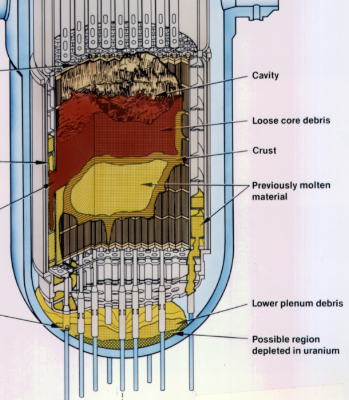
Corium movement after vessel failure:
The Three Mile Island nuclear disaster showed that fuel can melt unevenly towards one side of the reactor, rather than a uniform melt of the fuel. This behavior could cause melted fuel to fail toward one side of the reactor rather than a uniform failure. TEPCO’s meltdown analysis assumed a uniform melt but is based on a very limited set of data and does not include factors such as a LOCA, uneven melting or in vessel explosions.Chernobyl showed that melted fuel with enough heat and mass can travel laterally for a considerable distance.
TMI accident document via the NRC
TMI core melt diagram:
Chernobyl corium travel paths inside the building:

Our recent research also shows the torus downcomer bellows joint to be a weak point in the design. The joints in the downcomer pipe intended to allow the pipe to flex with movement of the torus also creates a weak point where corium could break through before reaching the inside of the torus. Other estimations on the ability of corium to move laterally show opportunities for corium to end up in the torus room that surrounds the torus. The illustration below shows a 15 meter lateral line, this is similar to the lateral corium flows at Chernobyl.

Corium may have traveled out pipe penetrations, or out one side of the bottom head then out the downcomer paths into the torus room. It could have also done both where some escaped out into pipes and the remaining into the east side torus room.
The torus room itself was in much worse condition than units 2 or 3. There were what looked like directional scorch marks, heat damage to power cable insulation and excessive small debris in the standing water found in the lower torus room. This is the condition on the west side of the torus room, the east side would likely be far worse if it was possible to inspect that area.
The radiation readings in containment, around the building and in the torus room taken together point to the east side torus room as the general location of the melted fuel. With this being the case, TEPCO’s decommissioning plan will need to be changed. It also causes more concerns about radiation and contaminated substance releases from the plant. What is unknown at this point is if the fuel could have traveled further down inside the torus room that only has 2.7 meters of concrete foundation, or further laterally through the wall or openings between the torus room and other interconnected rooms between the reactor building and the turbine building.
* TEPCO’s inspection of the torus room of unit 1 recorded readings of 10 E 8 to 10 E 9 in the lower water in the torus. TEPCO gives this range rather than a single number for these levels in the water and cites an instrument failure. They cite that the meter stayed at these extremely high levels until they removed the instrument. TEPCO frequently cites instrument failure when they run into readings beyond a meter’s capability or where they are unsure of the accuracy when they reach an instrument’s capabilities. The meter returned to a lower reading once removed indicating it was exposed to a very high source but the actual numbers could not be established with confidence.
Additional reading and documentation:
TEPCO Unit 1 Torus Room Inspection:
http://www.tepco.co.jp/en/nu/fukushima-np/images/handouts_110803_01-e.pdf
TEPCO TIPS Room inspection
http://www.tepco.co.jp/en/nu/fukushima-np/images/handouts_120705_03-e.pdf
TEPCO documents on the unit 1 containment inspection:
Oct 12 water analysis
http://www.tepco.co.jp/nu/fukushima-np/images/handouts_121012_05-j.pdf
Underwater in drywell
http://www.tepco.co.jp/nu/fukushima-np/images/handouts_121012_04-j.pdf
Oct 12 work information in Japanese
http://www.tepco.co.jp/nu/fukushima-np/images/handouts_121012_06-j.pdf
Oct 11th work doc in Japanese
http://www.tepco.co.jp/nu/fukushima-np/images/handouts_121011_10-j.pdf
Drywell water document in English
http://www.tepco.co.jp/en/nu/fukushima-np/images/handouts_121010_01-e.pdf
Oct. 12 handouts in English
http://www.tepco.co.jp/en/nu/fukushima-np/images/handouts_121012_03-e.pdf
http://www.tepco.co.jp/en/nu/fukushima-np/images/handouts_121012_04-e.pdf
http://www.tepco.co.jp/en/nu/fukushima-np/images/handouts_121012_02-e.pdf
TEPCO page with photos and video
http://photo.tepco.co.jp/en/date/2012/201210-e/121012-01e.html
Unit 1 core damage by TEPCO
http://www.tepco.co.jp/en/nu/fukushima-np/images/handouts_111130_04-e.pdf
Videos of unit 1’s containment inspections on our YouTube Channel
http://www.youtube.com/user/SimplyInfo
Reactor meltdown bottom head failures:
http://www.osti.gov/bridge/servlets/purl/6124656-R8y05j/6124656.pdf
Fukushima disaster wiki:
http://en.wikipedia.org/wiki/Fukushima_Daiichi_nuclear_disaster
Peter’s analysis of unit 1:
http://brainmindinstrev.blogspot.com/2012/07/fukushima-station-black-out-delusion.html
This article would not be possible without the extensive efforts of the SimplyInfo research team
Join the conversation at chat.simplyinfo.org
© 2011-2023 SimplyInfo.org, Fukuleaks.org All Rights Reserved
Content cited, quoted etc. from other sources is under the respective rights of that content owner. If you are viewing this page on any website other than http://www.simplyinfo.org (or http://www.fukuleaks.org) it may be plagiarized, please let us know. If you wish to reproduce any of our content in full or in more than a phrase or quote, please contact us first to obtain permission.
Pingback: SimplyInfo (Eng trad) Unité 1, où est le combustible fondu | FUKUSHIMA INFORMATIONS | Scoop.it
Pingback: Fukushima : Unité 1, où est le combustible fondu ? « L'info 'Autrement' cftc hus
Pingback: Osservatorio sulla crisi nucleare a ottobre 2012 | Backyard World
Pingback: Unit 1, Where The Melted Fuel Is ? #nuclear #fukushima #occupy #todolist wake up on nuclear issue ! | Occupy Belgium | Scoop.it
Pingback: The Progressive Mind » Up to 1,000,000 sieverts per hour outside Fukushima Unit 1 containment vessel — Still too hot to attempt measuring other areas (PHOTO & VIDEO)
Pingback: Le corium de Fukushima 1F1 : posé sur le plancher de la salle du tore 1F1 ?